


So there you are, slowly creeping up the hill behind 12 other vehicles. Even though the speed limit is 55. Tempers are flaring and horns honking.
And why, pray tell, are you poking along instead of cruising along? Well, guess what’s at the head of this little peloton? Of course: chugging along, resplendent in rainbow colors and peace signs, straining at the bit, is a venerable VW bus, manifesting “I think I can, man” (in German, of course).
As hard as the engine is working, it runs the risk of overheating – except that, like all engines, it has a cooling system to prevent – or at least put off – such a misadventure. As long as enough air goes over it, the engine can more or less keep running. (If it gets to the top of the hill and pulls over and stops to cool the engine, it might actually catch fire because the fan has stopped, meaning that there is nothing except still ambient air to cool the engine – and that might not be enough.)
Most other vehicles – including VWs – have long since opted for the extravagance of a water-cooled engine. The liquid can pull heat away faster, and, as long as you have enough water and antifreeze, you’re unlikely to overheat. Or burn up.
We’ve been living in an air-cooled semiconductor world for a long time. Most chips cool in ambient air that gets blown through by a system fan. Phones get no such cooling. And high-end processors might get their own personal fan mounted on top – cuz they’re just that awesome.
Our current cooling conventions have mostly worked – aided by the fact that we lay our chips out in a planar fashion on PC boards. But we’ve been lurching towards adding a dimension (or a half) to that world, what with silicon interposers allowing closer cohabitation and with visions of die stacking.
As we go more and more vertical, we’ve had to surmount numerous technical and cost challenges, but the one that hasn’t seen much in the way of an unambiguous solution is getting the heat out of the middle of a stack of dice. We all know it needs to be done; doing it is quite another thing.
Over the last few years, we’ve seen hints of ways to move from air cooling to liquid cooling, but, at semiconductor scales, it’s tougher than simply building cooling channels into an engine block and tacking on a radiator. Microfluidic cooling comes with its own practical challenges, so at Georgia Tech, Thomas Sarvey and company, led by Assoc. Prof. Muhannad Bakir, worked with Altera to take some solid steps towards working through some of the classic barriers.
The cooling projects had two main goals: get the heat out (obviously) and deal with thermal crosstalk – where one hot chip shares its heat with an otherwise cool neighboring chip. That latter bit can be a challenge when the victim chip is more temperature sensitive – analog, RF, MEMS, etc. The resulting paper presents a number of technology ideas for the various different challenges.
Make room in the interposer
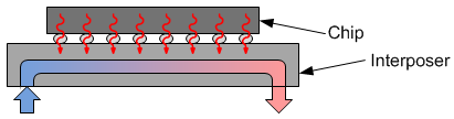
One of the critical questions is where the fluid should flow. The chamber or passages through which it goes act as a heat sink, with the fluid being recycled off-chip through some other heat exchanger. One option is to place this heat sink in the interposer. By doing this, you don’t have to worry about the chips themselves; you handle the cooling in the custom interposer you had to create anyway while relying on standard, off-the-shelf ICs.
Problem is, in order to do that, you need a thick interposer. And that makes it hard to put in through-interposer-vias that will go through to the bottom (whether the interposer is silicon or glass). If cooling will happen in the interposer, then a better way is needed of building those interposer vias.
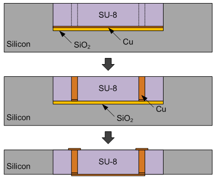
Their idea was to build the vias in a polymer instead of silicon (or glass). They took a wafer and etched out a well, putting an oxide etch-stop at the bottom and a copper seed layer above that. They then filled the well with SU-8, which is an epoxy-based photoresist.
They were then able to pattern and etch the vias in the SU-8, electroplating to fill the vias with copper, grinding away the back of the wafer, and metallizing the top and bottom of the vias. Because they were simply trying to assess the quality of the vias, so they set up connections for 2-port measurements.
Their measurements showed 78% less insertion loss than oxide/silicon vias, making this an option for higher-performance vias in a thick interposer.
Fluidic microbumps
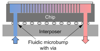
The next issue they addressed deals with heat sinks in the chips instead of the interposer – but with the interposer being used to deliver the fluid. In other words, the fluid would have to get from the interposer to the chip and then back again.
To handle this chip-to-chip-like flow, they came up with fluidic microbumps: annular bumps with a via through them. The critical part is that the fluid can’t escape at this interface. A leaky fluidic microbump would be as effective as a leaky radiator in a car.
To prove this out, they also needed to create a “chip” with a fluidic heat sink. They did this by patterning and etching into the chip backside of the wafer to create a forest of “pins.” This becomes a space wherein the liquid can flow, with the pins providing lots of surface area for exchanging heat. They can seal the space off with a glass cover, keeping the liquid contained within the pin forest.
From this they proved out no leaks and good fluid flow. So this provides a way for a chip to exchange cooling liquid with an interposer – or with another chip, in a 3D stack.
Coupling between Processor and Memory
Next they tackled the problem of thermal crosstalk. Even with fluidic cooling, crosstalk can still be a problem if there’s a single fluid circuit, moving the hot liquid through (or under) cooler chips. So one conceptual solution is to use separate interposer heat sinks for each chip.
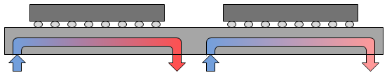
They simulated the effect of this with an Intel i7 processor positioned 1 mm away from a neighboring memory. The idea here is that you want the memory as close as possible to the processor so that they can communicate as fast as possible. But the closer you make them, the more the processor is going to heat up the memory. Because they were using standard chips, they kept the heat sink in the interposer rather than relying on a change in the dice to make this work.
In the standard configuration, which puts a heat spreader over the two chips and a metal heat sink on the processor, the simulation heats the processor up to 102 °C, while the memory gets up to 86 °C under their operating assumptions (which I’m omitting, but which you can find in the paper). Cooled fluidically next to each other, without the heat spreader and metal heat sink, the temperatures dropped to 63 and 46 °C, respectively, showing not just better cooling, but also reduced thermal crosstalk.
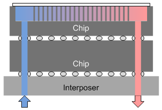
Things get a bit trickier if you’re trying to go 3D instead of 2.5D. Their solution here was twofold. First, they kept the processor at the bottom of the stack. While this might seem silly, since this keeps the processor away from cooling air, it again relies on the electrical connections to guide the heat down into the interposer, away from the memory. Then, to further keep the memory cool, they put a “thermal bridge” over the memory, which helps to draw heat from the memory and down the sides of the stack. Under the thermal bridge, a second microfluidic heat sink was used to draw this heat away.
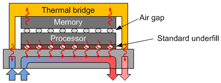
One obvious challenge here is the continued transfer of heat from the processor into the memory chip through the electrical interconnect and underfill. To help discourage this, they propose an air gap between the two chips to add insulation between them.
Of course, you still have electrical connections between the two dice, and they’ll transfer heat from processor to memory. The solution they found was to cluster the I/Os – and hence the vias and microbumps – away from the memory cells. That keeps the heat in the vicinity of the I/Os, but the memory cells themselves stay cooler.
The results here:
- With air cooling, both chips got up into the 75 °C realm.
- With simple fluidic cooling, both chips got up to around 65 °C.
- With their proposed stack, but with no TSVs modeled between memory and processor, the processor was still up near 65 °C (ever so slightly cooler than above), but the memory got only to about 40 °C.
- Including the TSVs, the processor got to 61 °C (since it’s also losing heat to the memory now) and the memory got to about 52 °C.
So clearly the TSVs are increasing the thermal coupling, but the memory still stays far cooler than in the first two baseline cases.
Hacking Stratix
Their final trick was to take an Altera dev board that featured a Stratix V device with a heat sink. They desoldered the chip and removed the heat sink. This exposed the backside of the die, allowing them to etch a pin forest into it, just like was done above. The cover they sealed onto it also had the microfluidic I/Os. They then soldered the modified device back onto the dev board.
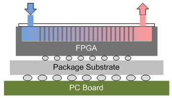
They instantiated processors in the FPGA. The idea was to see how many processors they could run before the thing got too hot, comparing a standard air-cooled version (stock with the dev board) against their fluid-cooled hack.
One of the catches was that they were relying on a diode in the corner of the chip to detect the temperature. But this won’t capture the gradient in the pin forest, so they ran their tests twice, reversing the fluid flow the second time around, in order to capture that temperature gradient.
With one processor running, the fluid-cooled version got to about 21 °C; the air-cooled one warmed to 43 °C. I won’t go through the whole table, but at 7 processors, the fluid-cooled version was still at about 22 °C, while the air-cooled one had rocketed to 61 °C, causing the over-temp light to illuminate on the dev board (the limit was 60 °C). So 6 was the max number of processors that could run air-cooled without building up too much heat.
Meanwhile, they took the fluid-cooled version up to 9 processors, and it remained at around 24 °C. And, as a bonus, because of the lower temperatures, overall power consumption dropped by 5% due to reduced leakage currents.
So, all in all, the team reported a number of practical solutions to fluidic challenges:
- Polymer vias for electrical connections in a thick interposer;
- Fluidic microbumps with vias for mating dice to dice or to interposers;
- Separate fluid circuits for separate chips to reduce thermal crosstalk;
- A new 3D stacking architecture for processor and memory, including an air gap between stacked dice, die-to-die TSVs clustered away from sensitive circuits, and a thermal bridge with its own separate heat sink in the interposer; and
- A way of creating fluid heat sinks by etching a “pin forest” (my term, not theirs) into the backside of a wafer.
So just think… someday your grandkids will be trying to do something that would be unimaginable using today’s electronics, only some component will be slowing them down. You’ll look into it and discover that somewhere in the chain of things is an old-fashioned air-cooled server, and there’s a big line-up of faster, cooler technology shaking their fists at this old thing that shouldn’t even be on the road anymore.
You can get more detail from their paper. It’s in the proceedings for the recent CICC show, so it’s not online yet. It will hopefully come up soon (or you can inquire with CICC). Full cite details aren’t available yet, but the title is, Embedded Cooling Technologies For Densely Integrated Electronic Systems, Sarvey et al.


Do you see this fluidics work leading to commercial liquid cooling of 3D chips? Or are there other big barriers?