If you want to minimize the power consumption of your system, you can’t wait until you have your design reduced to gates. Yeah, you can do some things there to help, but the big wins come earlier, at the architectural or RTL levels.
But how do you know at that point how much current your design will draw? In particular, dynamic current? Past approaches have used average activity rates or some such general number to give a squint-your-eye approximation, but it’s hard to get that number right, and it’s harder to get it right mode-by-mode and block-by-block.
What would be nice would be actual activity data. That would mean accessing every node in the design so that all nodes can have their power contributions included. FPGA prototypes won’t work, because all the nodes aren’t externally visible. And, as Mentor notes, even FPGA-based emulators, like Synopsys’ ZeBu systems, wouldn’t work because their full-visibility approach relies on JTAG to stream out the internals, which would be extraordinarily slow to do for every node on every cycle. (It should be noted that Mentor and Synopsys have a history of not seeing eye to eye on emulation patent claims…)
Mentor says that their Veloce emulators can run a suite of tests at speed, but there’s still an issue: capturing the results for use in a power analysis tool. The traditional approach to this would be to capture an FSDB (fast signal database) file and then use that file as input for power analysis. But that would be a ginormous file, and the writing and reading would become the rate-limiting step (partly because the data is written by signal but read by time).
Alternatives are to use VCD (still too slow) or SAIF (switching activity interchange format). SAIF gives only average activity information. Greater detail is available by providing more structural information ahead of time via a “Forward SAIF” file, but Mentor says that building this file requires detailed knowledge of the entire design and can be time consuming. So these traditional approaches tend to be used only for limited simulations on the order of tens of 1000s of cycles or so.
Mentor’s Veloce Activity Plot helps reduce the scope of data required by quickly showing where activity is greatest over time (without deep detail). You can then isolate those areas and have Veloce rerun those critical periods in great detail so that the power can be determined. But this is still more than an FSDB or VCD approach can handle gracefully.
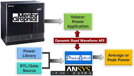
So Mentor did something rather unusual: they fraternized with the enemy. Cautiously. In general, they compete with Ansys, but they don’t compete with Ansys’s PowerArtist power analysis tool. They wanted to be able to deliver data to that tool without divulging the internals of how that data is stored and structured. So they obscured all of that detail by providing an API that PowerArtist can use to capture data on the fly.
In other words, no more saving a file as an intermediate step: the circuit activity is observed on the emulator and passed in real time to PowerArtist, where power results are calculated.
(Image courtesy Mentor Graphics)
Mentor calls this tool the Veloce Power Application. It’s not just a Mentor utility that overlays an existing PowerArtist installation (sold separately); it’s a full integration. So when you get the Mentor tool, you’re also getting the PowerArtist tool buried inside.
You can get more info in their announcement.