

The sun is mass of incandescent gas, a gigantic nuclear furnace
Where hydrogen is built into helium at a temperature of millions of degrees
– “Why Does the Sun Shine?,” They Might Be Giants (originally from the album “Space Songs,” 1959)
NASA’s Parker Solar Probe reached its first perihelion (closest approach to the Sun) on November 5. At that time, the probe was flying approximately 15 million miles above the Sun’s surface at 213,200 miles/hour, winning the spacecraft the titles of the Solar System’s fastest and closest heliocentric spacecraft. At its closest approach, the Parker Solar Probe will hurtle past the Sun at approximately 430,000 miles/hour (700,000 kph).
Smokin’!
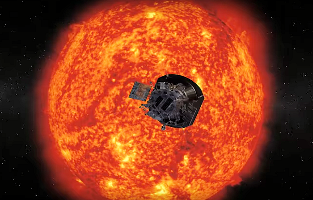
Figure 1: The Parker Solar Probe survived the first of 19 close approaches to the Sun on November 5. Image Credit: NASA/Johns Hopkins APL
The Parker Solar Probe’s primary science goals are to trace how energy and heat move through the solar corona and to investigate the forces that propel the solar wind and accelerate other energetic solar particles. Traveling aboard the Solar System’s fastest heliocentric spacecraft are the Solar System’s fastest FPGAs: rad-hard MicroSemi (now owned by Microchip) RTAX4000s, manufactured in 0.15 μm process technology at UMC.
These FPGAs incorporate SEU-hardened, triple-redundant flip-flops that supposedly provide all of the benefits of Triple Module Redundancy (TMR) without the associated overhead—at least that’s what the data sheet says. There’s an on-chip scrubber to deal with any SRAM upsets that might get past the memory’s error-detection and -correction circuitry. In addition, the RTAX4000 FPGA employs a metal-to-metal antifuse configuration interconnect that should also be impervious to ion strikes.
Why call these RTAX4000s the Solar System’s fastest FPGAs? After all, they’re made with absolutely archaic 0.15 μm process technology. Well, at the Parker Solar Probe’s maximum orbital velocity, those FPGAs are cruising at nearly half a million miles/hour! That’s fast, although perhaps not what you might consider fast in typical FPGA terms.
During this first of nineteen close approaches to the Sun, the Parker Solar Probe flew through the Sun’s tenuous outer atmosphere, the corona, which consists of material that’s heated to as much as 3.6 million degrees Fahrenheit. Because coronal material is so diaphanous, it won’t overheat the spacecraft through conduction. However, the intense radiation streaming from the Sun is another matter. Without sunscreen protection, the spacecraft would be badly sunburned.
So, the Sun-facing side of the spacecraft employs a heat shield called the Thermal Protection System (TPS)—a 4.5-inch-thick (11.43 cm), ceramic-faced, carbon-composite shield—that reflects most of the radiation and absorbs a little. During perihelion, the shield will heat to about 2500°F on the ceramic-coated side facing the sun, but it will be only 600°F at the back. With some additional separation, autonomous attitude control (to keep the heat shield pointed at the Sun), and some active water cooling for the retractable solar cells, the spacecraft and its instruments will be kept at a relatively comfortable 85°F. Ain’t materials science wonderful?
Using Venus to Pull Closer to the Sun
The Parker Solar Probe will use seven Venus flybys stretched over seven years as gravity assists to shift its perihelia closer and closer to the Sun. During the first gravity assist on October 3, the Parker Solar Probe came within about 1,500 miles of Venus’ surface and performed a little science as it flew by. After six more Venus flybys to reorient its heliocentric orbit, the spacecraft’s final three orbital perihelia will take the probe to within 3.83 million miles of the Sun’s surface. That’s well inside of Mercury’s 36-million-mile orbit and more than seven times closer than the previous solar spacecraft mission record, attained by the Helios 2 spacecraft back in 1976. Thanks to the Venusian gravity-assist maneuvers, the Parker Solar Probe’s instruments will bathe in and study the energies within the Sun’s corona for a total of roughly 900 hours.
Because of the Sun’s intense radiation output, the Parker Solar Probe cannot communicate with the Earth for an eleven-day period bracketing perihelion. So the spacecraft’s fate is unknown for days after perihelia occur. That’s why, on November 16 at about 6:00 p.m. EST, mission controllers at the Johns Hopkins Applied Physics Lab in Laurel, Maryland were overjoyed to receive the spacecraft’s very first post-perihelion report. The probe reported that it had survived its first close encounter with the Sun and that all systems were operating well.
One of those systems is the FIELDS instrument suite, which is designed to measure the scale and shape of the electric and magnetic fields within the Sun’s outer corona. Throughout the Parker Solar Probe’s extended orbit, FIELDS will study the Solar System’s inner heliosphere in an attempt to understand the fields associated with coronal waves, shocks, and magnetic reconnection—a process where magnetic field lines explosively realign. The FIELDS instrument suite detects both AC and DC fields.
FIELDS measures the electric field surrounding the spacecraft using five antennas. Four of these antennas poke out beyond the spacecraft’s heat shield, where they’re exposed to temperatures of 2,500°F. The 2-meter antennas are made of a niobium alloy to withstand this extreme temperature. The four sunlit antennas measure the properties of the fast and slow solar winds. The fifth antenna, which is mounted perpendicular to the others, sits in the heat shield’s comfortable shade and allows the probe to construct a 3D image of the corona’s electric fields at high frequencies.
Meanwhile, a trio of magnetometers, each about the size of a grapefruit, measure the magnetic fields in the corona. A search coil magnetometer (SCM) senses magnetic field changes as the shifting magnetic fields induce voltages in the coils. Two identical fluxgate magnetometers called MAGi and MAGo measure the large-scale coronal magnetic field. The fluxgate magnetometers are designed to measure lower-frequency magnetic fields while the spacecraft is further from the Sun, where the magnetic fields vary at a slower rate. The SCM is more useful when the spacecraft is closer to the Sun where magnetic fields change more quickly.
Figure 2 shows the electric and magnetic sensor arrangement on the Parker Solar Probe.
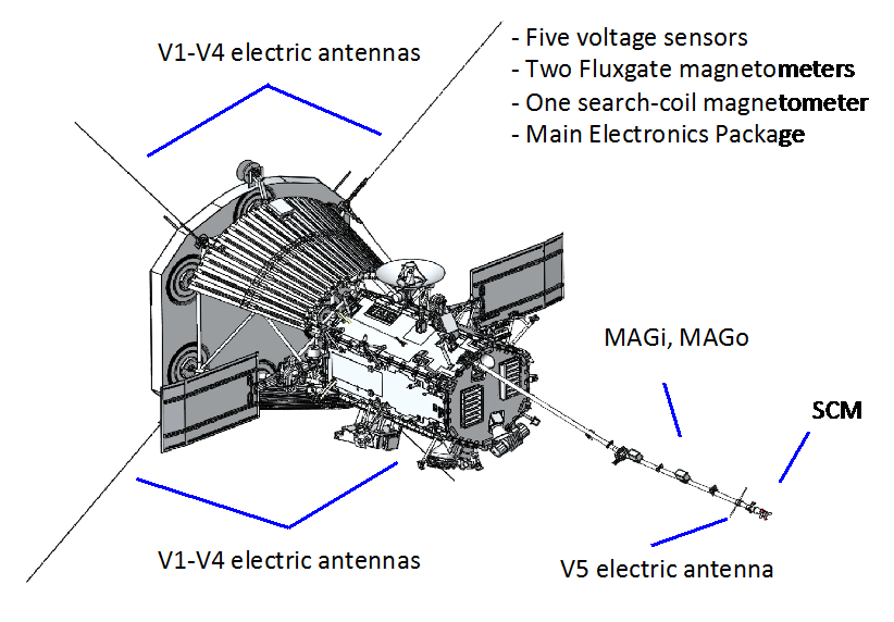
Figure 2: Electric and magnetic sensor arrangement on the Parker Solar Probe.
The FIELDS instrument suite was designed, built, and is operated by a team led by the Space Sciences Laboratory at the University of California, Berkeley. It was designed before the Parker Solar Probe was named the Parker Solar Probe. The original name for the spacecraft was the Solar Probe Plus.
Table 1 lists the measurement capabilities of the FIELDS instrument suite:
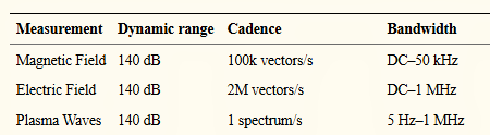
Table 1: Measurement capabilities of the FIELDS instrument suite
If you’re not impressed by these sample rates, just remember that this instrument suite is designed to operate more than 90 million miles from Earth while perched next to the Sun. (Yes, in this context, “next to” is a relative term.)
The spacecraft’s electric and magnetic sensors feed analog signals to the Main Electronics Package (MEP) mounted within the spacecraft’s structure. A Digital Fields Board (DFB) within the MEP conditions, digitizes, and processes signals from the electric-field sensors and magnetometers. A Teledyne SIDECAR ASIC digitizes the 26 analog sensor signals at 150 ksamples/second.
The SIDECAR ASIC was originally designed to support compact focal plane electronics for space telescopes. The Hubble Space Telescope’s Advanced Camera for Surveys currently employs a SIDECAR ASIC, and the James Webb Space Telescope mission will use one as well. The Parker Solar Probe’s DFB does not use most of the SIDECAR ASIC’s focal-plane-specific capabilities and merely employs it as a bank of thirty-two 16-bit ADCs. However, these are space-qualified ADCs.
Chock Full O’ Rad-Hard FPGAs
A Microsemi rad-hard RTAX4000 FPGA on the DFB converts the 26 digitized sensor streams into a range of time-domain and spectral-domain data products. All sensor signals are downsampled to 18.75 ksamples/second using an 8-point boxcar average.
A Data Control Board (DCB) also resides within the MEP. The DCB acts as the FIELDS instrument suite’s primary controller and serves as the main link between the spacecraft and the instrument suite. (Note that there are three other instruments on board the spacecraft as well.) The DCB receives and decodes commands from the spacecraft and distributes them to the FIELDS subsystems.
The DCB incorporates an embedded processor with associated CPU memory—consisting of a 32-kByte PROM, 2 Mbytes of SRAM, a 512-kByte EEPROM, and a 32-GByte Flash memory array for storage. The DCB’s embedded CPU is a 32-bit ColdFire processor IP core implemented in another rad-hard RTAX4000 FPGA. The ColdFire architecture is a RISC-ified version of Motorola Semiconductor’s 68000 processor from the late 1970s. That’s a true microprocessor relic!
Startup flight software for the FIELDS instrument suite resides in a rad-hard PROM while operational software, on-board scripts, tables, and other instrument parameters are stored in the EEPROM. Software and data stored in the EEPROM transfer to the DCB’s SRAM during start-up.
The same RTAX4000 FPGA that implements the ColdFire processor also implements the FIELDS instrument suite’s analog housekeeping, instrument control, spacecraft interfaces, bulk memory controller subsystems, and Radio Frequency Spectrometer logic. The DCB exchanges status and electric- and magnetic-field information with the spacecraft and tracks Mission Elapsed Time (MET) via spacecraft messaging.
In the November 16 “all’s clear” message from the spacecraft, the solid state recorder on the Parker Solar Probe reported that all four of its instrument suites had recorded a significant amount of data, which it started transmitting to Earth via NASA’s Deep Space Network on December 7. Presumably, the delay gave the Parker Solar Probe enough time to distance itself from the RF noise generated by the largest gravity-powered fusion reactor in the vicinity. The full download will require several weeks.
The Parker Solar Probe’s second perihelion will occur on April 4, 2019. During its seven-year mission, the spacecraft will experience 24 perihelia. The last three will take the spacecraft just 3.8 million miles from the Sun’s surface. Let’s hope those rad-hard FPGAs continue to crank away, despite their toasty environs.


This was a very interesting article and the CPU being implemented in a RTAX4000 FPGA was priceless. If it works well let’s do everything with the RTAX4000!
Not to nitpick but you have an international audience and the conversion to metric would be welcomed as you did in the first paragraph.