


These days, it’s all about keeping power down by all means possible. Power domains are a thing. Clock gating and power gating are a thing. Even applications can change the power state of the system.
All good, but let’s explore that last one a bit. In order for software to change the power, it has to go through the operating system. Which might seem kinda like this:
You: Hey, ‘sup, I’d like to set us up in this low-power mode now, cool?
OS: Really dude? You know, I’m pretty busy right now – lots going on. Keeping a bunch of plates spinning here, and you want another one, huh? <big sigh> OK, fill out these forms and get them back to me. Once I’ve finished my coffee, I’ll have a look. No promises.
You: Ummm… okay?
In other words, it takes time to make this all happen. And time isn’t your friend when saving power. If you’ve got an idle moment coming, but it takes half that time to shut down some power and then the other half to turn it back on again, well, you haven’t done much saving. Said simply, the faster you can react to power demands, the smaller the idle interval you can capture.
Which suggests letting the system save power with control at a much lower level: hardware. That conversation goes more like this:
You: Hey, ‘sup, I’d like to set us up in this low-power mode now, cool?
HW: Hold my beer.
You: !!!
But how do you do this? Sonics has been taking an active approach, which we looked at sometime back. But there’s one aspect that, at the time, they didn’t have in place yet. And now they do. It’s DVFS.
We looked at DVFS a way long time ago; it’s not a new concept. But, other than with Intel and other processors, it’s not something I’ve seen popping up a lot. It frankly takes some work, but Sonics is trying to simplify it some. And they claim to have the first IP that implements DVFS.
Reacting in Real Time
As a quick review, DVFS – dynamic voltage/frequency scaling – is the system’s ability to monitor temperature and demand and adjust the operating point (voltage and/or clock frequency) accordingly. Running a light load on a cold day? Crank that clock up, baby; get ‘er done. But doing the same thing while a movie enters its second hour of streaming? Yeah, we’re gonna take that one more slowly.
It amounts to a table that says: for such and such a temp, don’t exceed this clock speed. More or less. That provides a way to optimize power and performance on-the-fly based on actual operating conditions. And it’s a way to keep that dreaded blue mushroom cloud of death from appearing over your circuit.
So how does this work in real life? Sonics has added this capability to their ICE-Grain power management infrastructure. You may know Sonics for networks-on-chip (NoCs), but this is separate – although it can work with their NoC.
They model parts of a circuit at two levels. At the bottom is the notion of the “grain” – this chunk of circuitry will have a given clock and voltage value. A bunch of grains can be combined into a “cluster,” and a cluster maintains states for the grains it manages.
Controlling Your Operating Point
The following image shows the architecture at a broad level. And there are a number of options as to how this might work.
 (Click to enlarge; image courtesy Sonics)
Before we get into the options, let’s parse the drawing. The event matrix stores what to do when various hardware events occur. This drives a couple of things at a couple of levels. At the grain level, each grain has a power controller that takes notifications directly from the event matrix. But there’s also this operating point controller (OPC) at a higher level (exactly how high, we’ll come back to momentarily).
The grain controllers effectively implement clock and power gating, according to the policy established during design. The OPC, by contrast, controls the grain controllers, the voltage of various rails, and the frequency of various clocks. Between the two types of controller, you can choose, for instance, exactly which rail to use (grain controller) and what the voltage on that rail will be (OPC).
Here’s where the options come. Sonics expects many of their customers to use a single OPC for their entire chip. But another easily digestible option is to use one OPC per cluster. Or… some other setup; it’s not cast in stone.
One of those variations could have a clock or a voltage (both generically referred to as “resources” by Sonics) shared by multiple clusters. This would save the space that would otherwise be used to create a duplicate version of that clock or voltage. But here’s the thing: what if one cluster says to do one thing and another cluster says to do something else? You might end up with conflicting commands – and, in the worst case, you could end up in an unsafe configuration.
So, not shown in the picture is an arbiter between the OPC and the voltage and frequency blocks. You can also have an arbiter between the grain controllers and the grains. It receives the requests from any OPCs affecting that cluster or grain and ensures that, in the case of a conflict, you end up in a safe state.
Of course, if some guy says lower the power in one grain, but that same power rail is shared in another grain – and that grain needs higher power, then the arbiter is going to go with the higher-power setting to ensure that both grains can work. That means that the first grain will have higher power than desired or needed for the sake of the other grain. You could get around this by creating a new rail, but then you have the expense of the new rail. Same goes with clocks.
The DVFS Thing
Much of this ICE-Grain circuitry isn’t new – it’s been out there for a while. What is new is the DVFS capability added in. Each OPC can manage four tables; each table handles four resources, for a total of 16 per cluster. If that’s not enough, you can even cascade OPCs to do more.
The ultimate resource tables are separate; the local tables contain pointers to the resource tables. This is because it’s entirely likely that various clusters will share states. So, rather than replicating the details of that state in each cluster, the pointers let those states be shared, saving space.
This means that those arbitration circuits are going to need to include consideration of voltage and frequency when deciding what a “safe” state is. Going back to those possible conflicts, we now add this one: What if one cluster wants to crank a shared clock and the other wants to crank a shared voltage? If that operating point falls outside the safe zone, then the arbiter is going to have dial one of them back.
Then there’s this minor little question: how do you, as a designer, know how to populate those V/F tables? Well, that’s a job for characterization. And it will obviously vary by chip and by mode and by… Yes, this is best well thought-out ahead of time. You could easily imagine power policies getting spaghettified if done willy-nilly.
So you do the characterization, but how do you get the numbers into the tables? The UPF file has a role in specifying the power policy, but it doesn’t have all of the constructs necessary to completely specify these details. So Sonics has a tool called EPU Designer that manages not just the DVFS stuff, but also all of these ICE-Grain-related settings. (EPU stands for Energy Processing Unit.) The UPF file participates in that process, but it’s only one input.
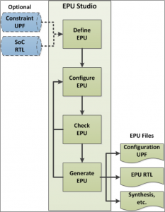
(Image courtesy Sonics)
So you should be able to specify what you want from your power management options, and the tool will output the RTL for various circuits, the files for synthesis et al, and a modified UPF that contains the relevant portions of the power policy.
So if you’re looking for a faster, more reactive way to manage your local power states, this should give you a low-level hardware option that will let you save more power during more, shorter idle periods.
More info:


What do you think about Sonics’ DVFS approach?
DVFS has been around for years, the main problem is you can’t verify it in SystemVerilog because none of the models handle dynamic power. So you have to trust the tools or go to SPICE level.
I’ve spent over a decade on Verilog-AMS and SystemVerilog committees trying to fix that, but nothing has budged. If you want it fixed (anybody), let me know.
What I’d like to see is asynchronous design with FDSOI body-biasing for control – that’s more robust since you only have one control knob.
Interesting… I wonder if Sonics has any comment on the verification question… or would one simply be trusting, in this case, the IP (rather than a tool).