

Ah, spring is here, and analog is in the air!
Um… yeah, that sounded better in my head than on paper. Guess it’s why Shakespeare never did any odes or sonnets to analog.
Be that as it may (and being that it’s May), this spring has seen analog announcements from two sources. Not sure if that’s a coincidence, but it does mean we’ve got some analog to discuss.
The two stories are pretty different, although that would be partly because the two companies have rather different positions in the analog EDA domain. One of them – Cadence – is dominant, and the other – Synopsys – is trying to crack the Cadence nut. By anecdotal report, that’s proving to be a pretty thick-hulled nut.
Synopsys Goes Visual
So let’s take them in chronological order. Synopsys announced Custom Compiler, building on their existing Custom Designer. And their efforts are based on two notions:
- Constraint-based analog design hasn’t gone well, and
- FinFETs are hella hard to lay out for custom designs. (To betray some of my East Bay provenance…)
The first point reflects one of the many historical (hysterical?) attempts to provide some level of analog automation – most of which have been resisted for lack of trust (and perhaps threat to job security?). Analog gurus are about as stubborn a nut to crack as the Cadence nut that Synopsys is pounding on, and attempts at automation have mostly been met with a suspicious, “Yeahhhh, no.” It’s hard to convince these guys that a tool could do as well as they could.
There is a kernel of truth in that suspicion, but there are ways to help; then the challenge lies in convincing designers that, overall, they’re better off with the help than without it. Constrain-based design was a recent such attempt at help. The designer specifies layout constraints, and then the tool dutifully sorts through the constraints and creates a layout meeting those constraints.
But, according to Synopsys, this has simply been too fussy a process. There’s too much to write, and it’s too easy to get things slightly wrong or to leave something out. And you have to admit that a text-based approach isn’t necessarily going to appeal to those have spent years perfecting their graphic layout skills.
Constraints aren’t going away, but, like so many such helpful technologies, some new tools are abstracting away the constraints. They’ll still be there, as we’ll see in a moment, but lurking under the works instead of front and center.
The second issue is the curse of the FinFET – especially for analog. The whole notion of analog should comprehend continuity – continuous variables and infinitely variable tuning; real numbers and uncountable infinity. FinFETs break that, however, since you have to have an integral number of fins. On top of that, you have many more variables that can be, well, variable. That makes optimizing for yield particularly difficult. Synopsys claims that designing analog circuits with FinFETs takes three times as much effort as compared to designing with traditional planar transistors.
Granted, Custom Compiler isn’t just for FinFETs – they claim that STMicroelectronics, for instance, is using the tool for FD-SOI design. But FinFET design is one of the key motivators.
To address these issues, Synopsys is bulking up with four “assistants.” The first is the Layout Assistant, and it’s the basis of what Synopsys is calling, “Visually Assisted” design. In other words, it’s back to the graphics approach, but with ways of making the details go faster. Layout can be done manually, but mouse guidance can help to automate tedious details like creating pin taps and cloned connections.
Next comes the Template Assistant. Custom Compiler comes pre-packaged with a number of templates. Designers can select these templates for key structures; layout will already have been completed. You’re not stuck with those templates, of course; you can make changes, and then you can save a modified template – or even a completely new circuit – as a new template for future re-use. This is where those constraints come in: while the user operates graphically, the stored details include constraints.
Following that is the Co-Design Assistant. This is a nod to the fact that few circuits are fully analog anymore, and a decreasing number of circuits are purely digital. But the two design methodologies are so different that neither side wants to subject themselves to the other side’s approaches and tools. So this assistant acts as a bridge from the custom tool to the digital design tools. It makes mixed blocks viewable from either digital or analog tools. There’s only one representation of the design in the design database, so this is simply a viewing or presentation issue, not a fundamental design structure issue.
Finally, there are a number of In-Design Assistants. These reflect the increasing use (or, in digital, these days it’s the exclusive use) of real-time checkers to validate designs as they’re done, rather than waiting until completion to do a check of an entire chip. Synopsys says that ECOs can be particularly nasty with FinFET designs, blowing up large portions of the chip. The idea here is to fix them right away, while they’re still small fixes. In-Design Assistants include DRC, electro-migration verification, IR drop analysis, and RC extraction.
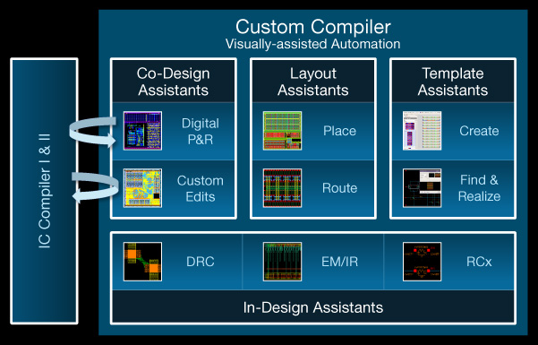
(Image courtesy Synopsys)
Tracing Cadence
Meanwhile, across town, Cadence announced their Virtuoso ADE Design Suite. You might think of this as a rebundling of their existing analog tools (perhaps with some environment-level tweaks), and, in fact, there may be some of that, but Cadence is keeping their old bundling as well. So no one has to make the change. Which makes me assume that they share the underlying technology so that they won’t have to maintain two totally separate sets of tools independently of each other.
Here again, we have four components, but with a very different focus. The spotlight is on verification and, in particular, on the increasing importance of designs in industries that require traceability. That’s been the case for aerospace and other so-called safety-critical industries for a long time, but now automotive is jumping in, along with medical and industrial.
The big picture here is that, before you do your design, you do your planning – including a thorough enumeration of design requirements. Each requirement tells the designer about something that he or she needs to create, but that’s no good if it’s not followed up by proof that it works. And that’s the traceability angle.
Each requirement gets tied to a set of tests, and the sum total of the tests is then tracked and reported in the tool. In theory, if all the requirements are mapped to the right tests, then, when the tests all pass, you have, by definition, met all the requirements. And if anyone asks for proof, you have it ready at hand.
This has been a thing with software for a long time, and it’s easier to manage with digital. Now Cadence is bringing traceability into the analog realm, with ADE Verifier as the owner of this feature.
The other three components of the tool are:
- ADE Explorer, for basic block simulation, Monte Carlo analysis, corner analysis, and block-level results tracking;
- ADE Assembler, for putting the blocks together into a full chip, centering the process for manufacturing, and design migration to different processes; and
- The Variation Option, likely to be needed only by designers working on advanced nodes or with FinFETs; the focus here is on yield.
ADE Verifier rides above them all (or… perhaps to the right of them), providing a regression environment, a high-level view of all results, a bridge to digital (sound familiar?), and requirements traceability.
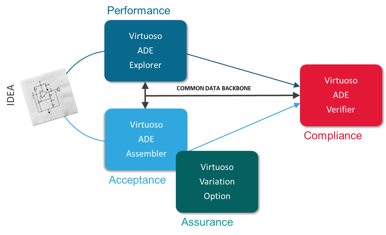
(Image courtesy Cadence)
There are other tools – not least of which is DOORS – for capturing and tracking requirements. Some of them are pretty old and rusty, but they’re still in use, and they dominate that landscape. Companies looking to implement traceability with analog may already have such tools. So ADE Verifier has to work with them.
There is, at present, no dynamic connection to DOORS. Requirements can be exported from DOORS and then imported into ADE Verifier. And, if requirements changes are made within ADE Verifier, those need to be exported and re-imported into DOORS. In other words, there’s no single requirements database if multiple tools are in play. (The “common data backbone” in the figure above refers to the design data, not the requirements data as shared with another requirements management tool.)
Cadence says that, at present, they don’t feel the demand from customers to build a dynamic connection, but if that demand materializes, they can prioritize that feature.
And that’s our Analog Spring for this year. Time to mow the lawn, fertilize the flowers, clean the central air filter, and finish up that comb filter.
More info:
Cadence Virtuoso ADE Design Suite


What do you think of Cadence’s and Synopsys’s analog announcements?