

So you build a circuit with a couple of transistors here and a couple of transistors there and you want to see how it’s going to operate. So you’ll simulate (or do signal integrity analysis or whatever other study you’re interested in). But you need to tell the tool about your circuit. So… do you just say, “Yeah, I’ve got a couple transistors here and a couple resistors there – please go calculate”?
Ah, if only it were so simple. Of course that won’t work – because it ignores all of the unstated interactions between the elements and other parasitic structures in the silicon substrate. Back when circuits were small, that meant manually building a more complete model that included the extra resistors and capacitors (and perhaps the occasional inductor) and putting that whole thing through the tool.
Of course, you had to specify process and operational corners – so-called PVT (process, voltage, and temperature) corners, so that added some work, but, all in all, it did the job. When circuits got bigger, we got automatic extraction tools that could take devices and figure out all of their parasitic values based on specific layout. Less manual work, less error. We’ve talked about extractors before, most recently last fall.
Well, let’s face it: this whole corner thing has gotten out of control. Analog has always had a complicated corner story, but, even with digital, the number of corners continues to grow. One big contributor to that is multiple patterning.
With double-patterning, you take what should be a single mask (where distances between features are fixed) and you split it into two masks. If you align those masks perfectly, then you’re golden. But in reality, overlay errors between the two masks mean that some features may shift relative to others. We recently looked at some ways that manufacturing can ensure better overlay performance, but, while they reduce the amount of variation, they don’t eliminate it outright.
So now one corner might be mask 2 shifted to the right. Another would be a shift to the left. Perhaps others for up and down? And nominal? And what about combinations of left-and-up? Right and up? And so on…
And that’s just with two masks. Imagine quadruple patterning. Yes, this is a thing. Each of those shifts on mask 2? They could also happen on mask 3 or 4. Or on mask 3 and mask 4. Or on any combination of direction and mask.
Why is this an issue? One simple reason: the time it takes to run this extraction process. Traditionally, each corner is more or less an independent run, so processing time increases linearly with the number of corners. Go from 4 corners to 8 and you have to wait twice as long for the results.
Corners aren’t the only challenge, by far. Another is the precision needed for enormously complex new devices – principally FinFETs.
 Digging into this requires a review of how this whole process has historically worked. Ideally, you want as accurate a result as possible. That would normally mean using a “field solver,” which meshes up the entire 3D geometry and solves Maxwell’s equations throughout. Maxwell was a pretty smart dude, so this works pretty well – except for one thing: it takes a long time.
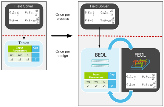
The way we’ve resolved this historically is to use field solvers when developing a process and then to derive from them tables that abstract away and simplify the results. These tables take a while to populate, but the key is that you do it once for a process. Then, for each design built on that process, the extraction tools use those tables instead of redoing the field solution, and that saves oodles of time.
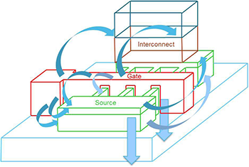
And it’s worked well up until recently, when complicated silicon devices – typically represented in what are referred to as the “front-end-of-line” steps (FEOL) (as contrasted with the many layers of interconnect that make up the “back-end-of-line,” or BEOL)* simply confound the ability of these table-driven approaches to deliver good accuracy. A knee-jerk reaction to this might be to decide that the era of tables is done – that we need to knuckle under, throw the tables out, and consult Maxwell every time. That would suck.
These challenges – corner craziness and table troubles – summarize some of the big reasons that Mentor wanted to make some changes to their xACT parasitic extraction tool. And, those specific challenges aside, processing speed is always an issue in a time of enormous chips growing to gargantuan size.
Don’t repeat geometry
So let’s take their solutions one at a time. The way they’ve approached corners is remarkably simple. The calculation process has three major conceptual steps: take in the silicon layout to learn the geometries in a generic way, then apply the specific numbers for a specific corner, and then go extract that circuit. This happens for every corner.
The thing is that, from corner to corner, the actual circuit doesn’t change. Only the corner parameters change. And, as it turns out, computing the geometries is actually more work than extracting the parasitics. So they’ve changed how the tool works so that it sucks the circuit in only once. It can then apply new corner parameters in succession on that same geometry rather than having to redo the geometry every time.
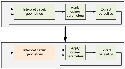
So, while the older approach has a linear response to the number of corners, now each corner adds only 15-20% to the processing time. (OK, that’s technically still linear, albeit with a gentler slope… but you know what I mean.)
Calling Maxwell
When it comes to the accuracy problem, they’ve had to concede to Maxwell, but not entirely. There are specific areas (generally FEOL) that need the accuracy. Others don’t. They’ve got a way of deciding which approach to use, so they keep both at the ready and pick either a solver or tables as they go. This means some tables still need to be created as the process is rolled out, but the solver gets used on a design-by-design basis as well.
While the solver-based steps will be slower than their table-based predecessors, they’ve gotten some of that penalty back by speeding up their table-based algorithms.
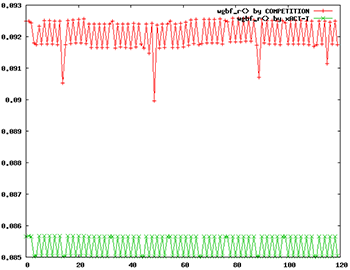
They also note that they use only deterministic algorithms – nothing statistical like “random walk.” They say this gives more stable results and accuracy in the attofarad range (remember when “femto” seemed small?). In the following graph, the red is a statistical competing approach; the green is xACT. The vertical axis represents capacitance in femtofarads. There was no “golden reference” when taking this data, so the absolute value (and the difference between the two) isn’t significant. The point is the occasional red outlier points that they attribute to stochastic approaches.
They also have what they call a “Boundary Condition Flow.” This is for the earlier stages in the design of a highly repetitive design, like a memory or FPGA, where tiles are stepped and repeated to build the full die. When working on the tile itself, it helps to predict what the parasitics will be given the expectation of neighboring tiles, but without actually laying out multiple tiles. Once you do fill in the full chip, you’d run a full extraction run again; this is just to help while designing the base circuit.
Divide and conquer
At the same time as they’ve done all this, they’ve also changed how they handle parallel computation. Much of EDA has been moving towards parallel divide-and-conquer approaches, but how you conquer – and how long it takes – depends on how you divide. A traditional approach has been to tile up a chip and then have different processors or computers handle different tiles. This approach works, but it requires some deft handling to stitch the boundaries back together – and this is a compute-intensive process.
Mentor has shifted to net-based partitioning. This means that, as much as possible, they try to keep neighboring nets together in a single partition. That minimizes the amount of dependency that different partitions have on each other. As you can imagine, with a single long net, it might interact with lots of different nets in many different neighborhoods along its extent, so it’s not always possible to do a perfect job of this, but they say that it’s better than tiling.
All in all, even with the improvement added by the use of a solver, they claim that they often see performance improvements of two to three times (Cypress claims to have seen a 10x speed-up). (Actual speed will, of course, depend on how many servers you throw at the problem.) Still, if greater accuracy can be achieved along with greater performance, seems like that’s generally a win.
*There’s also the hilariously nonsensical “middle end of line,” or MEOL, for local interconnect.
(First and last images, as well as the components for the third image, are courtesy of Mentor Graphics.)
More info:


What do you think about Mentor’s parasitic extraction improvements?