


I should probably start with a confession. Clocks and oscillators have never been my strong suit. I get the concept of oscillation and I get the fundamental function of a crystal or other resonator, but there have been some aspects that have always bugged me – and yet I never had occasion to wrestle with them. Until now.
We’ll come back to the specifics of this in a moment, but I start with this comment simply to note (or perhaps warn) that I approach this topic with some level of naïveté. The benefit of that is that I may end up questioning things that don’t usually get questioned; the downside is that I may end up looking stupid. Of course, I risk the latter with every question I ask, so I’m somewhat inured to that possible outcome.
I should also note that, for experts in this realm, some of this stuff may seem highly remedial. But part of my thesis here is that many digital system designers experience a rise in cortisol levels when dealing with the unfortunate analog islands that are required for a complete system. And clocks are definitely the most common example of that.
We don’t necessarily understand the clock circuitry through-and-through; we follow a recipe. If the reference circuit says to connect up the resonator with these caps and resistors and that op amp in this configuration, well then, by Jove, we do that and, with great relief when it works, hie our little behinds back into the safer and saner digital realm.
This story was stimulated by an interesting conversation I had with Sand 9 at the MEMS Executive Congress in November. You may recall that they make piezo-based MEMS resonators and oscillators. One of my take-aways from the discussion and mental wrangling can be summarized as follows: increasing integration and abstraction aren’t always the rule.
Let’s start by rummaging through the products that Sand 9 and their competitors offer; we can pick apart several components.
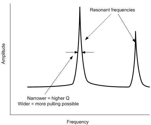
- There’s the resonator itself. This can be implemented lots of different ways depending on the frequency and quality factor (Q) required. An LC “tank” will work; crystals are classic; and MEMS is now in the game, with cantilevers (“flexural mode”) working at lower frequencies and bulk or surface mode (BAW/SAW) contributing at higher frequencies. A resonator will have a frequency response with spikes at resonant frequencies. I simplistically view the Q as the width of those peaks. The narrower and sharper the peak, the higher the Q. The wider the peak, then the more “slop” there is. And it turns out that some slop isn’t always bad, as we’ll see.
- A resonator resonates only when supplied with feedback. And not just any feedback; the phase matters. Again, simplistically thinking, picture a child on a swing (which is a resonator). If you provide a push at just the right time – when the swing hits its top point, then you’ll keep the swing going. If you try to push at any old random time, you’re simply going to have a frustrated child. And no one wants that.
- Then there’s temperature compensation. Depending on the resonator, performance may change as the temperature goes up or down. That could be due to slight changes in resonator dimensions or properties (like softness). If a fixed frequency, independent of temperature, is needed, then some way of countering this natural deviation is required.
Can I get some feedback please?
The trend in our industry is overwhelmingly towards integration, encapsulation, and abstraction. Especially to a digital designer, you would think that the desire would be to skip over the whole oscillator design thing as so much analog black magic. “Please, you take care of all the feedback amplifier mumbo-jumbo and get those poles and zeroes where they belong, because I don’t know my poles from my Czechs.”
And I’m sure there are plenty of realms where this would apply. The overwhelming interest in Internet of Things (IoT) and wearable gadgets, for instance, is bringing in a whole world of new designers from other realms who don’t know – and don’t care to know – about the detailed nuances of this low-level stuff. They’re focused on a bigger picture, and they just want the clock to work.
But Sand 9 doesn’t sell into the simple clock market. Their focus is higher frequencies for synthesizing RF signals. This is a much more rarified world where neophytes tread with trepidation. To the point where a lot of Sand 9’s customers are saying that they are perfectly comfortable designing the feedback loop themselves.
This brings us to the product offerings and the nomenclature. We’ll start simply with MR and MO: MEMS resonators and oscillators, respectively.* The difference? An oscillator is the whole resonator-plus-feedback-loop thing, and, if designed right, it will establish a sustained waveform. An MR device is just the resonator, which – critically – will not resonate unless you give it the proper stimulation in the form of a periodic input signal at a resonant frequency, which is a job for the feedback loop.
So the MO has the loop; the MR doesn’t. If you need the loop to get oscillation, then what good is an MR? Well, oscillator design is a tricky business. Sand 9’s Darren Weninger reminded me of the old adage, “Amplifiers oscillate and oscillators won’t.”
It’s also key to note that Sand 9 doesn’t sell directly to you and me. They sell to companies making SoCs, and the Sand 9 component typically gets co-packaged with that SoC. So, in particular given a higher-quality system-in-package (SiP) connection, you now have a choice as the designer of this system: do I put the feedback loop in the resonator chip or onto the SoC?
According to Sand 9, the bulk of customers are choosing to do their own feedback loop, which means that Sand 9’s focus has gone from full oscillators to simpler resonators. As a case in point, they sell an MR; they don’t have a pure MO listed on their products page.
Note that it might not be a simple “we can do it better” thing; my guess is that the cost of the feedback loop on an SoC is minimal. With an MO, however, it means adding an ASIC to the resonator. The ASICs tend to be bigger than the MEMS element, so they determine the size (and cost) of the final component. Sand 9 makes their ASICs separately and then mounts them upside down over the MEMS resonator.
With a pure MR, you can replace the ASIC with a blank wafer (simply for capping) and you’ll have a smaller, less expensive product. I’m not privy to the pricing, but I can picture much greater cost efficiency with an MR implementation. (And, in fact, Sand 9 said that they could see this picture changing if, say, a 14-nm SoC implementation turned out to be too expensive.)
Hopefully this will compensate…
Then there’s the issue of compensation. Nomenclature has “TC” at the beginning of the part name if a part is temperature-compensated. So a TCMR would be a temp-compensated MEMS resonator; a TCMO would be a temp- compensated MEMS oscillator. And, in accordance with the prior discussion on feedback, Sand 9’s initial focus has changed from TCMOs to TCMRs.
Temperature compensation gave me a real headache, because the notion of taking one frequency and transforming it into another arbitrary one is not obvious to me. Note that I don’t mean changing the original frequency, but taking the original frequency and then, elsewhere in the circuit, changing it; taking fR and not replacing it by, but transforming it into fR ± Δf.
Because, after all, that’s what compensation sounds like. You start with a resonant frequency that has drifted due to temperature, and you wave your magic wand, and “poof” – it’s now back to where you want it.
Well, that’s not quite how things work. And there are various options for temperature compensation. The most effective is to limit the amount of drift that happens in the first place. We saw that Sand 9 does this by layering oxide and silicon, which have opposing temperature coefficients, and so they compensate for each other naturally. But it’s still not perfect, if perfection is what you want.
There remain a couple of approaches. One is that, rather than compensating the frequency, you can compensate the temperature. And, in fact, some of the Sand 9 products have heaters built in. If things get too cold, you can turn on the heat and bring the local temperature back to where you need it.
So, of course, this means that you need a temperature sensor as well, which is integrated in with the heater and resonator. And, as far as I can tell, it works only for heating; I haven’t seen any integrated air conditioners…
But let’s say you’ve tried everything else and there’s still more compensation to be done. This is where I was driving myself nuts, because a resonator will resonate only at discrete frequencies. You can’t get it to resonate at just any old frequency. And that resonant frequency is, at least to a first order, dependent on two things and two things only: the dimensions of the resonator and the speed of pressure waves (essentially, the speed of sound) through that material. This establishes the nature of reflections and standing waves that, at the right frequency, can occur.
So it would seem like you can’t change this frequency – unless you change the dimensions or the wave speed somehow (and those are the things that change with temperature in the first place). If that’s the case, then, if the resonator is indeed going to resonate, you need somehow to change that frequency into a different one perceived by the rest of the system. The resonant frequency of the entire loop becomes the relevant measure.
The classic way to adjust frequency is to mess with the feedback phase. I came at that concept naively, from a first-principles standpoint, without convenient abstractions like Nyquist plots. And I couldn’t figure out how stimulating the resonator early or late would work. Coming back to our child-in-the-swing analogy, it’s like pushing the child earlier or later in order to change the swing’s frequency: it shouldn’t work that way.
The Sand 9 guys were very patient as I tried to visualize what was going on here. And I found various discussions online that made me feel not quite so uninformed (apparently this isn’t a topic that was settled 30 years ago). And it turns out that here is where imperfection in the MEMS device has some benefit.
Remember the Q thing? The width of the frequency-response spike? Well, if it’s perfect – if Q is infinite – then you’re out of luck. The spike would be a vertical line. Because then, the only way to get the resonator to resonate is to give it the exact stimulus frequency. But with a little bit of slop, well, now we have some more flexibility.
The idea is that there’s a narrow window within which you can still drive the resonator into resonance. This is often referred to as frequency pulling. The width of that frequency response spike means literally that there is a range of frequencies in that vicinity to which the resonator will respond. You sneak the feedback in a little earlier or later than perfection would suggest, and the resonator can still resonate.
It almost seems a bit Dopplery to me: the feedback provides either a slightly accelerated or slowed signal, and the combined system responds by adjusting the frequency until – and this is the critical point – the loop phase is zero. In other words, thinking about what’s going on inside the resonator, this means that a new input signal (call it a pulse) arrives just as the internal reflection from the prior pulse returns, and the two reinforce each other.
So, having emerged from that thicket, how does this affect Sand 9’s approach? Well, here again, it turns out that their customers are opting to do their own compensation, perhaps for reasons similar to the feedback motivation. So instead of TCMRs, you might see TSMRs: “temperature sensing MEMS resonators.” They have all the sensors and heaters and such needed for generating a compensated oscillator, but the feedback loop and compensation circuits are handled by the SoC.
After all is said and done, what this reflects is not a desire for more integration and abstraction, but a preference for doing it themselves. There aren’t a lot of places where that’s the case (although, truth be told, analog circuits will probably be one of the last places where you see deathgrips loosened).
Looking around at other approaches we’ve seen, SiTime uses a PLL to adjust the final frequency. PLLs have a component that changes the game: a voltage-controlled oscillator (VCO). That gives you a knob for adjusting frequency that crystal and MEMS resonators don’t have. Meanwhile, Silicon Labs integrates their compensation onto the same chip as their resonator.
So… yes, we’ve talked about some of this stuff before (as those links show). But always with me avoiding those nagging questions – an urge I failed to resist this time.
The upshot is that, while some corners of the market will happily accept clock devices that have the work already done for them, others are still willing to do the hard work of building and compensating oscillators for quality and/or cost reasons.
* This is how Sand 9 names them; you’ll often see X instead of M, which originates with crystals. SiTime, another MEMS oscillator vendor, appears to use the X nomenclature rather than substituting M for their devices.
More info:
Silicon Labs (clocks and oscillators)


Do you carefully design your oscillators or go the recipe route?
Interesting example of how a sloppy Q factor can actually be useful.
For those situations where the low Q factor in MEMS isn’t so useful (and there are many examples of that) – Crystal is still the answer.
I wouldn’t say it’s “sloppy” in the conventional sense. Anything with a finite Q – including crystals – has some slop. As far as I know, the Q of high-quality MEMS actually competes well with crystal.
Sand 9 would point to some issues that crystal has that MEMS doesn’t have (see the link in the 5th paragraph – “recall” – for more on that.)