


Verifying internal design states is the unheralded bugbear of chip design today. Even the preliminary step of identifying and exercising the panoply of operating modes is fraught, largely due to design complexity. As an extreme example, transistor counts for Intel’s newest chips now top 1.4 billion. (See: http://www.anandtech.com/show/4818/counting-transistors-why-116b-and-995m-are-both-correct.)
The introduction of random test methodology several years back helped ease the burden of creating sufficiently comprehensive tests. However, few would leave the task of verifying critical cases strictly to chance – and for good reason. Consider the travails I witnessed recently at one Mentor customer, a Bay Area semiconductor company in the high-performance network infrastructure market. The customer found that in one case, its entire regression suite only achieved 5% of a moderately-sized internal-state functional coverage goal due to the dual requirements of creating pre-conditions and then hitting an interesting internal-coverage case once the pre-conditions were met.
How do you get around this staggering shortfall without drowning in the task of designing, implementing and managing a full suite of directed tests? I’d like to suggest at least a partial answer by describing an approach to verifying a command processing pipeline.
What about stalls in the pipeline?
Consider a five-stage pipeline that processes a command with operands. The processor supports eight commands – CMD1 through CMD8. Under ideal circumstances, a new input command is accepted by the pipeline every cycle, and a command completes every cycle. As with all pipeline-based processors, however, stalls can occur in this pipeline when one of the stages takes longer than one cycle to complete. Thus, this simple pipeline can serve as a decent proxy for the more general problem of verifying internal-state conditions in the presence of effectively-unpredictable pre-conditions.
One verification task is ensuring that certain command sequences proceed through the pipeline. Specifically, all combinations of back-to-back commands must be exercised. For example, CMD1 followed by CMD1, CMD1 followed by CMD2, etc. Another goal is exercising these same back-to-back command sequences with one, two and three different commands in the middle.
The diagram below summarizes the sequences targeted for verification. The blue-shaded commands below are the ones to care about from a coverage perspective. The grey-shaded boxes are the commands whose specific values are unimportant, apart from the ensuring they are different from the commands that begin and end the sequence.
Figure 1 – Command-Sequence Examples
Here I should note that I’m using a UVM environment for this block, though an OVM or other transaction-based verification environment would work in a similar manner. Stimulus is described as a UVM sequence item containing a field specifying the command (cmd) as well as fields for both command operands (operand_a, operand_b). A UVM sequence running on the sequencer is responsible for generating this stimulus, while the driver converts the command described in the sequence item to signal-level transactions that are applied to the processor’s interface.
Figure 2 – UVM Environment
This verification scenario presents a couple of challenges, including how to describe the full set of desired sequences. It’s possible, of course, to carefully create scenario sequences using directed tests, but this would be a significant amount of work. Another option is leveraging random generation on a single-command basis and hoping to hit all the cases. The fatal flaw here is efficiency, which is hampered by random generation’s inherent redundancy and the fact that the constraint solver doesn’t comprehend the targeted sequential goal.
Pipeline stalls present a second challenge. From the perspective of a test writer, these stalls are unpredictable. Despite careful efforts to design a command sequence to apply to the pipeline, what is actually processed by the pipeline may be quite different than what the writer intended.
Describing the stimulus space
Describing and generating the command sequences is a classic input-stimulus problem, one that can be solved in part by a small handful of so-called intelligent verification tools on the market today. (Mentor’s offering is inFact, though the other two major EDA vendors offer tools with similar goals, as do several startup companies.) First, we create a set of rules that describe the sequence of five commands. Note that each command in the sequence is described by four graph variables. The rule description is shown below, with the graph-variable declarations and graph-sequence annotated. inFact is the basis for what follows, though the approach is generalizable to other tools, as well.
Figure 3 – Command-sequence Rules
The graph, shown below, provides a visual representation of the stimulus space. The graph integrates within a UVM sequence and creates a series of sequence items to be sent to the sequencer and driver. The illustration shows a graph expanded to the implementation specifics of cmd1. Note that the graph provides a straightforward way to view the stimulus space and verification process.
For each of the five commands in the sequence, select a command and operands to issue, and read in a state from the testbench that indicates whether the pipeline is stalled.
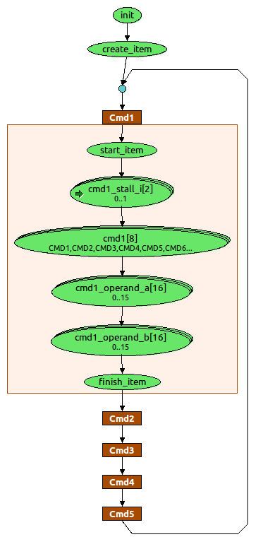
Figure 4
Targeting verification goals
The next step is describing the stimuli set, to be generated by the tool, that corresponds to the verification goals. At a high level, the main interest is in crossing the following variables in order to realize the command sequences described earlier:
- Cmd1 x Cmd2
- Cmd1 x Cmd3
- Cmd1 x Cmd4
- Cmd1 x Cmd5
However, it’s also important to account for the requirement that commands in the middle of sequences must be different from the starting and ending commands in the sequence. The four constraints like the one shown below address this requirement. Note how the constraint below describes the restrictions on a three-command sequence. In this case, the verification goals call for the command in the middle of the sequence (cmd2) to be different than the command at the beginning of the sequence (cmd1) and the command at the end of the sequence (cmd3). This constraint, and the other three like it, are linked to the corresponding cross-coverage goals.
Figure 5 – Coverage Constraint
Reactive stimulus
Efficiently describing comprehensive stimuli isn’t much use if the design doesn’t actually accept them. Avoiding this problem means selecting a tool that generates reactive stimulus based on state information from the environment. The key is an ability to take advantage of the current state of the environment and the currently-uncovered scenarios to make rapid progress to coverage, even when the tool isn’t able to directly control the environment state.
In this case, the environment provides a way to query whether the first stage of the pipeline is stalled. The pipe-stall information indicates whether the expected verification scenario was applied. The stall information can be referenced in our coverage constraints so that, if the pipeline stalls during application of a command sequence, the coverage constraint will evaluate to false, causing the tool to retry that command sequence in the future.
Conclusion
Yes, in the world of increasingly nuanced technology, handling a design’s internal states presents a large problem, though one that can be solved. That customer I mentioned at the beginning of the article? The one whose regression runs were only hitting 5% of a particular internal-state coverage goal? With a small amount of integration work and one short simulation with a new “intelligent” tool, it was able to achieve full coverage of that verification goal. For the group of engineers I worked with, reaching this type of difficult-to-hit coverage goal was critical to the success of their project. Indeed, their ability to achieve the verification goal efficiently – both in terms of engineering investment and simulation efficiency – was truly intelligent testbench automation.
Matthew Ballance is a verification technologist at Mentor Graphics. Write to him at matt_ballance@mentor.com. His last article in EE Journal, “Trading Cards and the Art of Verification,” was published in January 2011: http://www.techfocusmedia.net/archives/articles/20110127-mentor/.


Mentor’s Matthew Ballance discusses how to verify internal processor states. What approaches have you been using to get good internal-state coverage?