


Depending on which article or social media post you read, people are either excited about self-driving vehicles or they’re petrified. (Truck and taxi drivers are more of the latter, although for different reasons.)
And what makes people so nervous? To sum it up in one word, algorithms! And if our only experience with algorithms is social media, then we ought to be afraid. But, realistically, there’s no lack of awareness of the seriousness and safety requirements for automated vehicles. Cars have their own safety standard, ISO 26262, one of the specialty standards under the umbrella of IEC 61508.
In other words, the design practices well honed in the aerospace industry are being adapted for automobiles. Cars may not fall from the sky when things go wrong, but they can damage a lot of people and things. So vehicles will be designed much differently than Facebook feed algorithms. (Whether they’ll be successful is still an open question…)
Ultimately, auto manufacturers own the safety of the cars they market. But they assemble those cars from subassemblies made by suppliers. And anyone making those subassemblies will be building hardware and, in many cases, loading up software. And all of those bits need to work together, safely and predictably. So the final assembly is blessed as safe based on the processes and tests done by the automaker, supplemented by proof and tests and arguments from the makers of each subassembly. And on up the line.
Which means that, at some point, you come to components (hardware or software) that were made or verified by tools. How do you demonstrate that the tools and the flows in which they’re used are providing safe, predictable outputs?
This is something that aerospace folks have had to deal with for years. In theory, you have to prove that the tools you use are working correctly. Or, at the very least, that, if something goes awry, you’ll know – you don’t want any goofs quietly being absorbed into the overall design, only to cause some mayhem later. So it’s been common practice for tool vendors to do their own certification so that their users can rely on that rather than having to do it all themselves.
Well, the same situation is now in place for automotive design. And ISO 26262 has a specific category for tools and your level of confidence with them: the Tool Confidence Level, or TCL. No, not the scripting language. And no, that wasn’t the internal project code name for that very first giggly Elmo. Rather, it’s a three-level score you give to a tool or flow, with safety-related automotive stuff needing to achieve the highest level, TCL 1.
There’s a distinction between a tool and a flow, and it’s no mystery. As a tool user, you have little control over the tool itself – how it’s coded. The flow, however, is all about how you use the tool – so you could be on the hook for that. But Cadence has taken some steps to relieve you of much of the effort needed for either one in the form of “safety kits.” Each kit contains a safety manual – how to use the tools to ensure safety – as well as a series of Tool Confidence Assessment documents.
It would be nice if these docs contained page after page of outright proof of safety. While that’s possible for some use cases on some tools, much of this happens by argument, essentially giving an evidence-based rationale for why the tools should be safe.
You might think, “Hey, I can prove that my synthesis engine works correctly by running some verification or validation checks afterwards.” Well, yes, but then how do you prove that the verification tools don’t just happen to miss the error that the synthesis tool just happens to create? That might sound over-paranoid, but errors can spring from assumptions, and, if a basic assumption is made by a company making both design and verification tools, then that incorrect assumption might feed both tools. This is why, for example, it’s good to get IP from one vendor and verification IP from another – so that you have multiple points of view as cross-checks.
Cadence probably wouldn’t appreciate an interpretation that says you should get your design tools from one EDA guy and your verification tools from another. And, realistically, within a big EDA company, the different tools are created by different teams, so it’s unlikely that you would see this scenario. Unlikely enough that most people, for most designs, don’t worry about it at all. But when life and limb depend on it, you go the extra mile.
The process involves lots of head-scratching about what kinds of things could go wrong, what would happen if they did go wrong, and how you would know if they went wrong. And they’ve done this for tools and flows – it can help if your flow includes tools that provide cross-checks on each other.
With respect to individual tools, Cadence has a long list of tools for which they’ve created documents (green in the tables below), with another long planned list (blue in the tables). You’d think that, having gone through the pain of doing this, they’d be done. But no, with each tool update, you have to redo the docs – at least to some extent. Cadence’s approach is to update their docs with minor tool updates, while generating a new set of docs for major revisions.
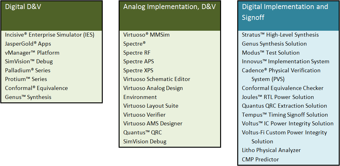
Figure 1. Individual tool TCAs. Green are done; blue is pending.
Once the specific tools are handled, then there are the flows. Cadence has, so far, documented two flows: digital design and verification (pre-implementation), and custom design and verification. On tap for delivery soon is the digital implementation flow.
The details of these flows matter, and they’re illustrated below. Each flow shows tools that could create incorrect data and tools that could fail to find an error. These are, of course, the tools that have individually been documented.
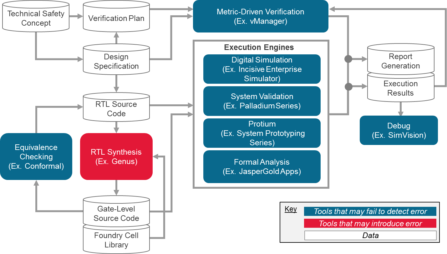
Figure 2. Digital design and verification flow
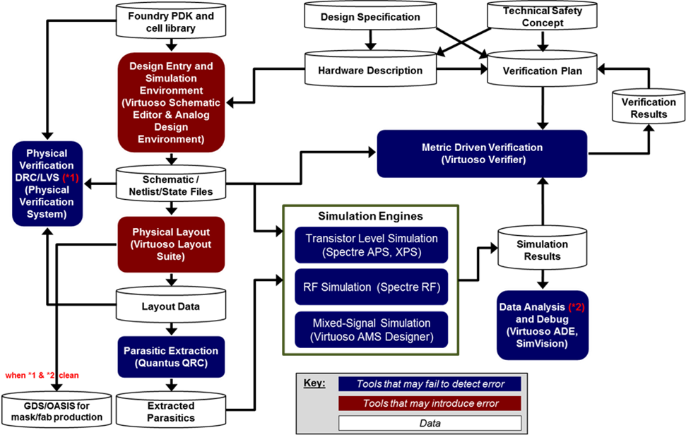
Figure 3. Custom design and verification flow.
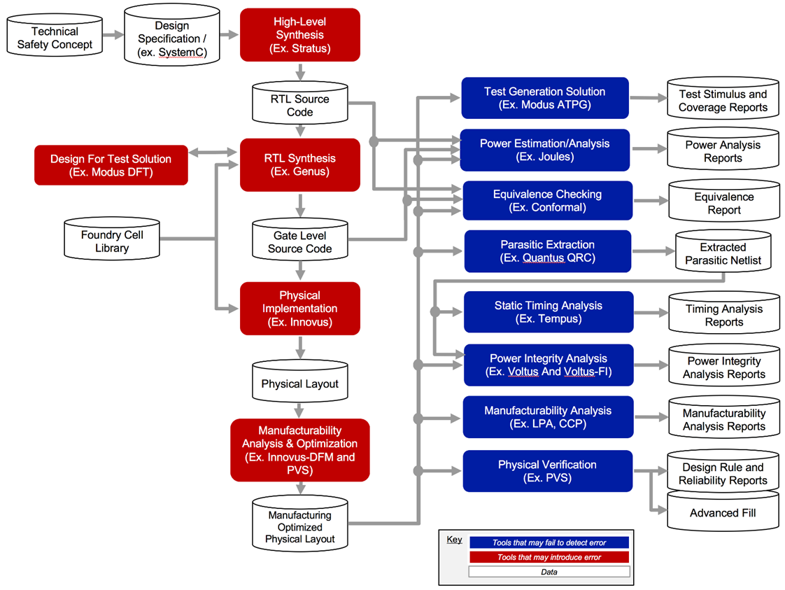
Figure 4. Digital implementation flow (pending).
(Flow images courtesy Cadence)
So what happens when you use a flow, but it doesn’t match these baseline flows exactly? Then you need to document the differences. So there’s still work, but a lot less work than if you had to document the entire flow. If a tool that you sub in for one of the Cadence tools is also documented, then you still save that time (but you still need to document the flow deviations). Anything you do that’s not pre-documented falls to you to handle.
Designing systems that are inherently safe is hard work, and the process surrounding it can feel like a burden. On the other hand, if you can sleep better knowing that that thing you designed is keeping the public in good hands, well, that’s worth something.
More info:
Cadence ISO 26262 TCL Compliance


What do you think of Cadence’s safety kits for automotive design?