Respin! Respin! Respin! Are you afraid yet? For three decades, the electronic design automation (EDA) industry has relied on that fear. They learned way back in the 1980s that the quickest path to the biggest budget when selling software tools was through fear of the dreaded, career-limiting IC design respin. Want to sell me something that makes my engineers more productive or my designs more optimal? Meh… Maybe. Want to sell me something that prevents me from taking the blame for a respin on my project? How much money do you need?
We have talked lately about how EDA needs to learn a new trick, and nowhere is that struggle more evident than when an EDA company briefs technology editors on a non-respin-related technology such as the world’s #1 enterprise-class board design system. You’d think the business case for equipping your multi-billion dollar engineering company with the best tools for designing board-based systems would be pretty obvious, but Mentor walks you through it anyway, almost apologetically pointing out that productivity, collaboration, complexity management, cost-control, quality, and reliability are things that your organization might want to consider in the equation.
Wait, you’re not gonna save me from a respin? Why are we even talking?
Hang on a minute, though. There is light at the end of this tunnel. Mentor is showing clear signs of partnering with customers to develop a wide array of important design tool capabilities – particularly in the area of board-based system design – that are not sold based on fear and respinophobia. It’s refreshing almost to the point of being unsettling. In fact, Mentor’s whole approach to PCB/system tools the past few years has undergone a major change, putting them much more squarely in line with the demands of actual mainstream electronic product design.
The new version of Xpedition announced this week is a case in point.
Rigid-flex design and high-speed design are no longer specialized, boutique design arenas reserved for the elite. But mainstream PCB tools have traditionally left us to accomplish these types of design with tricks and workarounds, mostly centered on convincing our tool that we are really still doing the same old things we’ve always done. There are volumes of application notes and tribal tricks to get your tool to do rigid-flex by pretending that your design isn’t really rigid-flex. It works about as well as you’d expect.
With the latest Xpedition, Mentor has changed all that. The company has gone back to the drawing board and built in native support for rigid-flex and high-speed design. Yep, that means you don’t have to trick your tool anymore. You just tell it exactly what you’re doing. Weird, huh?
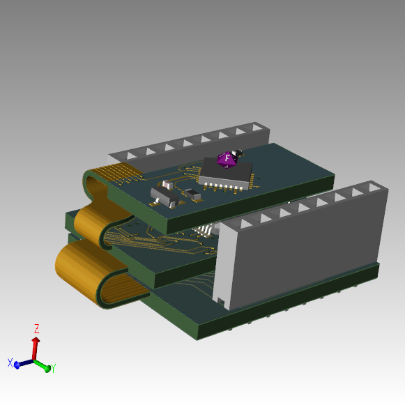
What does native support for rigid-flex actually mean? First, it means that you can define actual rigid and flexible outlines with different stack-ups. Before, you had to trick the system by specifying a single board outline with different regions for rigid and flex stackups. Now, the system understands that it must maintain signal integrity and honor design rules in both types of outlines, and in the discontinuities that cross outline boundaries. That includes new rules like bend-fold control with collision rules, curved routing with teardrops, hatched planes, and component placement in flex outlines. It lets you visualize your design in both folded and unfolded states and clearly pass your design intent to manufacturing.
Since the system now understands what a flexible outline is, it also knows that this part is supposed to bend, and you can define bend regions that tell where and how the board bends. This allows a host of new design rule checks including placement and plane metal rules, trace widths, corners, and vias, and the ability to do 3D analysis to detect component collisions and similar issues. Placement and routing now has different rules and constraints for placing components on any external surface – whether rigid or flex.
The new design rule checks allow detection of problems unique to folded/flex design and also integrate with MCAD to be sure that everything works within the intended enclosure. With the old “workaround” approach to rigid-flex design, you were pretty much on your own in terms of the unique challenges of folded/stacked rigid-flex boards. Now your design tool system can understand reality and help to make sure that what you pass to manufacturing will actually work. Electrical rule checking and design-for-manufacturing (DFM) checks also make a giant step forward by understanding the true nature of the rigid-flex design space.
Turning to the high-speed design side of things, Mentor has upgraded their popular “sketch router” capability. You can “sketch” a trunk where a bundle of signals are to be routed, and the autorouter will do the detailed work, conforming to your sketch. You can then edit the sketch, and the detailed router will move all of the affected routes accordingly. You can now also create “shield” traces within a trunk of traces, and the system will drop-stitch the vias as part of the shielding.
The system now also supports the (currently Intel-proprietary) “tabbed” routing for maintaining performance on high-speed nets. Tabbed routing comes in two variations – one of which looks like a zipper with stubs coming off normal traces that interlock with each other, and the other, designed for pin fields (such as in a BGA), generates curved traces that optimize performance. Mentor’s solution allows full interactive editing, modification, and deletion of tabbed routes – similar to that of any other routes.
Mentor’s routing optimization gives constant feedback on constraint adherence and provides control over tuning. It supports semi-regular tuning patterns and allows push/shove to be turned off routes adjacent to those being tuned (so you don’t get into that frustrating “squeezing a balloon” situation.)
Xpedition provides one interface to review all design rule checks, including both design-for-manufacturing and electrical rule checks. The latest release improves the performance of dynamic hazard detection, as well as graphical display and cross-probing between errors and the offending parts of the design.
The current announcement is only one of a series of announcements from Mentor that together form a comprehensive remodel of the company’s tool strategy for board-based design. From our perspective, this is a welcome change, as it maps the company’s tools much more closely to the reality of modern electronic product design, and it makes the technology more usable and capable for the mainstream designer.