


It wasn’t too long ago that we took a look at a new tool from Sage DA that could be used to create design rules in an automated fashion so that the resulting rules will be clean and consistent. It also provided a way to iron out any ambiguities in a design rule manual.
For those of you less deeply embedded in this space, what we’re talking about here is the ability to check a new chip design’s layout to make sure it doesn’t violate manufacturing rules. In order to be able to do that, we need to have a set of rules to test whether a specific IC meets the constraints of a given process. That way you ensure that no lines are too thin or spaces too narrow. (Oi, if only it were that simple.)
This Design Rule Check (DRC) happens before you bless a set of masks for production. But before you can do the tests, you have to figure out what that set of rules is going to be. That’s done informally in a design rule manual, but codifying those conceptual rules into hard rules that a computer can process is a lot of work. It’s a place where automation can save time and reduce errors.
Well, creating design rules is but a part of the problem solved. Once you’ve built a new rule, you then have to test it out to make sure you really got it right. And let’s be clear here, since we have tests upon tests: what we’ll talk about for the rest of this article isn’t the DRC test used to check a specific chip’s layout. What we’re talking about here is testing the rules when we create them to ensure that the rules are correct. Only when the rules are known to be good would we then apply them to a real layout (that last step being something we’re not going to talk about here).
Why would you create design rules manually when you have a tool that can create them in a more automated way? Well, if the automated tool doesn’t create rules in the format of the design rule check (DRC) tool that you happen to use, then you’re back to creating by hand.
Sage’s iDRM tool, which creates design rules, has its own format. It doesn’t create rules in the format of, say, Mentor’s Calibre tool – widely used for DRC. Design rules that can’t be read by your DRC tool… not so useful. Which is why you would stick with the old way of doing things: by hand.
So if the rule creation can’t be automated in this case, what about that other part – the rule testing? Let’s take a minute to look at what’s involved in that process. I’ll use an example that Sage provides (and the graphics below are courtesy of Sage). In Figure 1, we see a specific design rule outlined graphically.
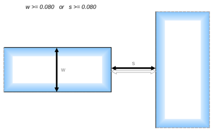
Figure 1. Graphic example of a spacing design rule.
This rule specifies a spacing requirement when the tip of a narrow line (on the left) approaches the side of another feature (on the right). If the line on the left is narrow enough – and that means that its width w is less than 0.080 [units], then the spacing s has to be greater than or equal to 0.080 [units] (I don’t know the units… it doesn’t matter… I’m going to omit them from here on out). The way they express this mathematically is that one of the dimensions – either the line width or the spacing – has to be greater than or equal to a limit. In this example, the limits for w and s happen to be the same: 0.080.
This, on its face, might seem a bit odd – you could imagine that, if w were larger than 0.080 units, then, by this rule, you can close the gap arbitrarily, and you might then end up with some nasty situations with really small s values that still pass this rule. But, if that situation is going to create a manufacturing problem (which it probably would), then there’s probably some other rule that deals with that eventuality.
In fact, there are lots of other rules, which Sage refers to as “background” or “fixed” rules (fixed in the sense that, while we mess about with this one rule, the others remain fixed). In particular, there is likely to be a minimum spacing rule saying that, no matter the situation, spacing can never be smaller than some limit. That rule would protect against loopholes in the more specific rules letting through something unmanufacturable.
So how do you go about testing this particular spacing rule? Well, you “simply” create test geometries. I put “simply” in quotes because, while simple in concept, this can be a lot of work, because you have to test each aspect of the rule, and you have to prove both that (a) good layouts invariably pass the rule and that (b) bad layouts invariably fail the rule. There’s no room for false positives or negatives.
Some test examples are shown below in Figure 2. The actual numbers are tough to see based on how the figure was created (starting with screenshots), so let’s go through them.
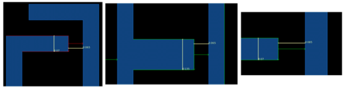
Figure 2. Some tests for the rule in Figure 1.
On the left is a test figure that has w at 0.07 and s at 0.065. This test should fail because both w and s are below the 0.08 limits. The rule says that at least one of them has to be above the limit.
The middle layout shows a fatter line on the left – w is 0.135, above the limit. s is 0.065, so still below its limit, but the rule says that only one of the two has to be high enough, so this layout should pass the rule. And vice versa, on the right: w is below the limit at 0.07, but s is 0.085, above the limit, so the test passes.
This is a pretty simple rule, so there aren’t a lot of other tests you would need. If you felt like it, you might create one with both w and s above the limit (although it’s logically covered by what we already have). And it’s probably a good idea to test the limit values themselves to make sure you don’t run into a “> vs >=” gotcha somewhere along the way. So maybe we’d have five tests here.
That wasn’t so bad, was it? Now… multiply that by, oh, let’s say a thousand, and toss in rules that are much more complex. Your work has just exploded.
This is where Sage’s new DRVerify tool comes in. You define the rules, and it creates test cases for them. In principle, you still create the design rules by hand using iDRM, but the tests are now created for you automatically. Given a particular limit, a test will be created on either side of the limit: one to pass and one to fail. The dimensions used for the test are determined by the process grid; the tests use dimensions that are one grid step on either side of the limit.
There is some chance that the tests could proliferate somewhat more robustly than you had in mind, exploding with more tests than you ever imagined might be possible. It is a computer, after all, and we know they’re more than willing to do whatever we say, no matter how self-destructive that might be. So users can apply constraints or seed the process with select tests, if desired, to help manage the number of tests. You can also search the generated tests to ensure that specific cases you want covered – like a regression set – are indeed in there.
Sage suggests, for example, that one way to approach this – especially in early days, when assembling the design rule manual – is to dial the constraints up very high to limit the number of tests created to a few simple ones (eliminating tests on combinations of variables, for example). Once that looks ok, you can ease up to generate more tests.
Why would you generate more tests? Well, DRVerify can perform one other task: it can check for inconsistencies between rules. So, for example, if another rule said that the minimum spacing always had to be greater than 0.09, then the middle test above would pass the specific rule, but it would fail the background rule. That could be flagged as an inconsistency.
All of this does take some compute time – it takes about a minute to create the tests for one rule. But that’s still way faster than you could generate the tests manually – and it’s more complete and less error-prone.
One last point: we positioned DRVerify as being useful for rules in non-Sage formats. You might, for a moment, wonder whether you could use the tool to verify the rules generated in the Sage format by Sage’s iDRM tool. And the answer is, “Not applicable”: you don’t need to, since the design rules created by iDRM are guaranteed to be correct by construction. (They just can’t be used in all tools…)
More info:


How does Sage DA’s design rule testing methodology sound to you?